A. Rogner
SIGRIST-PHOTOMETER AG, Hofurlistrasse 1, CH-6373 Ennetbürgen, Switzerland
Abstract
A new generation of continuous particulate matter concentration
monitoring instruments is presented, covering a measuring range of 0 to
1000 mg/m3. The laser-based scattered light instrument gives an
improved stability as well as excellent resolution in the low range. This
enables high concentration measurement as well as especially low emission
monitoring down to 0.01 mg/m3 with a resolution of 0.001 mg/m3.
The high stability of the laser light source, a purge air system avoiding
pollution of the optical interfaces and an automatic drift check system
allow a maintenance interval of three months. The monitoring is done in an
extractive sampling line heating the gas up to 160°C thus allowing the
monitoring of wet gases.
1 Introduction
Forced by governmental regulations with decreasing emission limits as the
new European directives 2000/76/EG for waste incinerators and 2001/80/EG for
power plants, the technology for reducing particulate matter emission has
been continuously improved over the last years. Latest state-of-the-art
waste incinerators and combustion facilities in standard operation emit
particle concentrations of 0.1 mg/m3 or even less (TÜV-Bericht:
936/806015, 1997).
To ensure a reliable control of these low emissions and the related
cleaning process, particulate matter measuring instruments also had to be
improved. These instruments should have at least a resolution of 10% of the
lowest emission values given above, i.e. 0.01 mg/m3, to make
changes detectable and to demonstrate the instruments functionability. On
the other hand, peak emission values in countries with more moderate limits
or for older facilities can reach up to 200 mg/m3. So a
multi-purpose instrument suited for installations in a variety of industries
and applications like waste incinerators, power plants, refineries, cement
kilns, etc. has to cover a broad measuring span with a high dynamic
resolution.
In addition, the new European Standard EN 14181 for quality assurance of
automated measuring systems and the new suitability requirements for
continuous emission monitoring systems in EN ISO 14956 brought further
requirements for new measuring equipment as automatic drift and reference
point check including logging functions.
2 Principle of detection
2.1 Scattered light measurement
The newly developed StackGuard instrument is based on its predecessors
CTNR and KTNR, which have been installed in about 350 facilities since more
than 20 years and successfully used in a variety of applications and
industries. Similar to these instruments, the StackGuard is using the
scattered light detection for particulate matter concentration measurement
(Fig. 1). A light beam with certain intensity is striking the sample. Due to
absorption and scattering at the dust particles, the transmitted light
intensity is reduced. This effect is used in the measurement principle of
opacimeters especially for high particle concentrations. To detect high and
also low particle concentrations, the detection of the scattered light is
necessary. In the StackGuard, a certain part of the scattered light is
detected under a 20° angle.
 |
| Figure 1: Scattered light measurement |
The intensity of the scattered light shows in this concentration range a
linear relation to the concentration of the particles, as long as the
particle properties like size, shape, color, or refractive index do not
change. As demonstrated in paragraph 4, a calibration of the instrument can
be done using a linear fit between the scattered light intensity and the
particulate matter concentration determined by a reference method. Using
this calibration, the read-out of the instrument can be displayed in mg/m3.
For different particle properties, the scattered light intensity and
distribution might also be different (Huber and Frost, 1998). For most
applications in dust emission measurement these variations are negligible in
the concentration range of interest and the linear fit is still appropriate.
In some applications, however, especially with a wide span of the
concentration or a variety of different fuels, the particle properties like
e.g. the size distribution are changing with changing concentration. In
these cases the best fit method for the calibration curve might be different
from linear, e.g. quadratic or logarithmic. Due to this fact, for all light
scattering CEMS, a calibration has to be done on-site after installation of
the instrument.
2.2 Optical setup
The completely revised setup of the StackGuard instrument is given in
Figure 2. The measurement is done in two phases:
Phase 1: The laser remains switched off. The zero points of the three
detectors are determined. This is especially important to reduce any
zero-point offset and thus improve the accuracy at low dust levels. The
laser is a temperature controlled semiconductor laser light source with a
wavelength of 650 nm.
Phase 2: The temperature-stabilized laser is switched on. The light
impinging on the two reference detectors and the 20° scattered light
detector is measured. The measurement reading is calculated from these
signals.
Using this two-beam method, a continuous determination and compensation
of all uncertainties and errors due to intensity changes and fluctuations of
the light source and ageing effects of the electronics is achieved. Any
additional drifting is well-proven to be below 2% per 3 months and can be
easily compensated by re-calibrating the instrument by inserting glass-rods
with a given opacity.
Moreover, the improved sensitivity of the light detecting circuits gives
a dynamic range of more than 105 for the scattered light intensity thus
covering a concentration range from 0.0005 mg/m3 PLA to 100 mg/m3
PLA. The appropriate measuring range is selected by automatic range
switching.
The signal ratio of reference detector inlet (3) to reference detector
outlet (7) gives an information on the pollution of the optical components
and is monitored continuously. When a certain limit is exceeded, a warning
is generated.
 |
| 1 |
Temperature-stable laser |
| 2 |
Partially permeable mirror |
| 3 |
Reference detector inlet |
| 4 |
Tilted mirror |
| 5 |
Flow cell |
| 6 |
Purge air shroud |
| 7 |
Reference detector outlet |
| 8 |
Scattered light detector |
| 9 |
Automatic checking unit, consisting of: |
| 10 |
Partially permeable mirror |
| 11 |
Attenuator |
| 12 |
Shutter |
| 13 |
Scattered light body |
| 14 |
Actuator for attenuator and shutter |
|
| Figure 2: Optical setup of the StackGuard |
An additional improvement in the StackGuard is an automatic zero and
reference point drift check system (see also Figure 2). Every 24 hours, the
system undergoes the following check procedure:
1. Measuring position: Part of the laser light is decoupled with a
partially permeable mirror (10). When the checking unit is in the measuring
position, the attenuator (11) blocks this checking beam. The shutter (12) is
open and lets the scattered light from the flow cell pass through. It is
detected by the scattered light detector (8).
2. Reference point check value: The attenuator (11) lets pass the
checking beam unhindered. It strikes the scattered light body (13) and
produces scattered light that is picked up by detector (8). The shutter (12)
is closed and blocks the scattered light coming from the flow cell.
3. Zero point check value: The attenuator (11) reduces the checking beam
intensity to 1%. The scattered light produced by the scattered light body is
picked up by the scattered light detector (8). The shutter (12) is closed
and blocks the scattered light coming from the flow cell.
The periodically detected values are compared with the nominal values. In
the event of an excessive deviation, a warning is given.
All these features described above from the highly stable laser light
source to the various self control mechanisms allow an extension of the
maintenance interval to 3 months, which gives significant relief to the
operators.
3 Extractive sampling system
For flue gases which are normally or occasionally saturated with water or
acid gases, e.g. after wet scrubbers or flue gas desulfurication units,
interference with optical measurement may occur due to fluid droplets also
scattering the light. To overcome this problem, the sample for the scattered
light measurement in the StackGuard is extracted from the stack and heated
in a sampling line up to 160°C. Some national regulations like PS 11 in the
U.S. even require extractive arrangements for this type of applications.
Figure 3 shows the complete setup of the StackGuard including the loop line
for sample preparation.
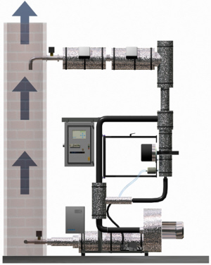
Figure 3: StackGuard measuring system including ring pipe
|
The sampling line (c) takes the sample from the
stack (d) at a flow rate of 60 m3/h using a blower (e). This
high flow rate is chosen for two reasons. One, to ensure representative
sampling, and second, to prevent deposits by using a high gas velocity
in the loop line. From this loop line, the sample for the photometer (b)
is taken with a flow rate of 35 l/min. The probe of the CTNR sampling
line in the stack uses over-isokinetic sampling with a factor of 1.5 to
reduce the relative error for changing gas flow velocities in the stack.
The absolute error is considered with the calibration of the instrument.
Using temperature controlled heaters, the sample temperature is kept at
a level of at least 160°C. The control unit (a) handles the operation,
control, display, and signal processing functions.
The photometer is built up in two completely
separated compartments. The first compartment contains all the
electronics, light source, detector, chopper, and the related optical
elements. The sample compartment contains the flow cell for the
detection of the particles by scattered light measurement (Figure 4).
The sample enters the flow cell from top (P1). A heated and filtered
purge air flow (S1) surrounds the sample stream with a protective
shroud, and additional purge air injection in front of the optical
lenses S2 prevents soiling of the optical surfaces L1 and L2. Sample and
purge air leave the cell at the bottom outlet (P2).
This setup makes the cell insensitive to any
changes of the signal caused by soiling even for gas streams with high
particle load. As given above, the drift of the complete instrument
including errors by potential deposits on the windows, is less than 2%
per 3 months and can be easily adjusted using optical control glasses. |
 Figure 4: Sample flow cell of StackGuard
 |
4 Calibration
All instruments are factory calibrated related to PLA (polystyrene latex
aerosol) spherical particles with a diameter of 1 micrometer to ensure the
linearity of the calibration over the complete measuring span. The on-site
calibration relating to the actual particle load usually can be done just by
inserting a fix factor between the PLA value and the real value in mg/m3.
Usually, this factor can vary between 1.0 and 40.0, depending on the
characteristics of the particles as size distribution, material, surface
structure, refractive index, etc.
For the calibration of the particulate matter CEMS in these low ranges,
exceeding accuracy has to be taken for the reference method. It is obvious,
that the accuracy of the calibration (and thus the accuracy of the
continuous measurement done later on) cannot be better than the accuracy of
the manual method. So either a well-known method like given e.g. in the
guideline VDI 2066 should be used, or paired data with two trains should be
collected for the manual method. The latter is especially the case, if a
well-known method is modified, or if the results are not satisfying. The
paired data approach will allow evaluating in a first step the accuracy of
the manual method before starting the calculation of the calibration curve.
To test the manual method, a plot of train 1 versus train 2 should be done,
where the slope should be near to 1 and the correlation coefficient should
be 0.95 or better. Otherwise the manual method has to be improved. The
method applied for the results given below is the manual method according to
guideline DIN EN 13284, part 1, April 2002.
5 Field test
To demonstrate the increased sensitivity and stability of the StackGuard
instrument compared to its predecessors, a test installation at a municipal
incinerator waste incinerator has been done. The unit was installed
specifically in the intermediate gas duct following the scrubber and ahead
of the flue gas nitrogen oxide control. It has been investigated within the
suitability test of the system (TÜV-Bericht 936/21202165/A, 2005).
The measuring systems were installed in a horizontal flue gas duct. The
inlet and outlet sections were at least three times the diameter. The duct’s
circular cross-section is 1.60 m in diameter. The intake openings of the
measuring installations were arranged at the measuring level, spaced less
than 0.3 m apart. The measuring level for the reference measurements was
located in the measurement volume of the measuring installations.
The particle emission of this facility is under normal operating
conditions around 1 mg/dsm3. Values between 0.4 mg/dsm3
and 2.4 mg/dsm3 have been seen during the campaign of 6 months.
An artificial spreading of the values by modification of the operating
conditions is no longer allowed according to EN 14181 standard. Two
instruments have been installed for 6 months and within this time two
measuring campaigns of 17, resp. 16 test runs using manual reference method
have been carried out. The measuring range used for this test was 0..1 mg/m3 PLA.
The results are given in table 1 and figures 5 and 6, respectively.
| Test run no. |
Particle concentration reference method [mg/dsm3] |
StackGuard Instrument 20 [mA] |
StackGuard Instrument 21 [mA] |
| 1 |
2.0 |
6.26 |
6.48 |
| 2 |
2.0 |
6.30 |
6.39 |
| 3 |
1.6 |
6.29 |
6.43 |
| 4 |
2.3 |
6.27 |
6.43 |
| 5 |
1.9 |
5.79 |
5.89 |
| 6 |
1.9 |
5.80 |
5.93 |
| 7 |
1.5 |
5.84 |
5.91 |
| 8 |
0.6 |
4.45 |
4.46 |
| 9 |
0.6 |
4.46 |
4.46 |
| 10 |
0.6 |
4.44 |
4.44 |
| 11 |
0.7 |
4.46 |
4.46 |
| 12 |
0.7 |
4.49 |
4.49 |
| 13 |
0.7 |
4.44 |
4.44 |
| 14 |
0.7 |
4.45 |
4.46 |
| 15 |
0.7 |
4.42 |
4.44 |
| 16 |
0.4 |
4.42 |
4.43 |
Table 1: Results of StackGuard on waste incinerator
| Regression analysis results: correlation coefficient: 0.93 |
| ------- |
confidence interval |
| ____ |
tolerance interval |
|
| Figure 5: Calibration of StackGuard No. 20 on waste incinerator |

| Regression analysis results: correlation coefficient: 0.93 |
| ------- |
confidence interval |
| ____ |
tolerance interval |
|
| Figure 6: Calibration of StackGuard No. 21 on waste incinerator |
Although the low values of the manual reference method have been at the
limit of this method, the statistical values demonstrate a good reliability.
Also both investigated instruments react very homogeneous. Full scale in the
selected measuring range of 1 mg/m3 PLA is corresponding to a
particulate matter concentration of approximately 12.5 mg/m3. The
lowest detected concentration was 0.4 mg/dsm3. The lowest
detectable concentration, which is mainly determined by the stray light
background, was determined to 1% of full scale in the lowest possible range
of 0 to 0.05 mg/m3 PLA, i.e. 0.006 mg/dsm3.
The tests reported in this paper have been successfully performed by TÜV
Rheinland in Germany, leading finally to approval of the StackGuard for use
with power stations and waste incinerators according to 13th and
17th BImSchV and TA Luft.
6 References
Huber, E. and M. Frost (1998), "Light scattering by small particles",
aqua, Vol.47
TÜV-Bericht 936/21202165/A (2005), Bericht über die Eignungsprüfung der
Messeinrichtung StackGuard der Firma Sigrist-Photometer in
Ennetbürgen/Schweiz
TÜV-Bericht 936/806015 (1997), Bericht über die Eignungsprüfung des
Staubmessgerätes CTNR der Firma Sigrist-Photometer, Ennetbürgen (CH)
Products: StackGuard